Beams are among the most fundamental structural elements in engineering. They resist loads primarily through bending, and understanding their behavior under different loading conditions is essential for safe design. I built a standalone MATLAB application that computes shear force diagrams, bending moment diagrams, and deflected shapes for any beam type under any combination of loads. This design-oriented project was supervised by Dr. Dipendu Bhunia.
The problem
When a beam carries a load, internal forces develop along its length. Shear forces act perpendicular to the beam's axis, and bending moments cause the beam to curve. Calculating these values by hand is tedious, error-prone, and impractical for complex loading scenarios. At the time, few accessible tools existed that could handle arbitrary combinations of beam types and loads with a simple interface.
Beam types supported
Simply supported: resting on two end supports, free to rotate
Fixed: both ends restrained from rotation
Overhanging: extending beyond one or both supports
Continuous: spanning more than two supports
Cantilever: fixed at one end, free at the other
Trussed: reinforced with cables or rods forming a truss
Computational analysis
The software takes beam dimensions, support conditions, and loading parameters as input, then computes the complete structural response. For any configuration, it generates shear force diagrams, bending moment diagrams, and the deflected shape of the beam.
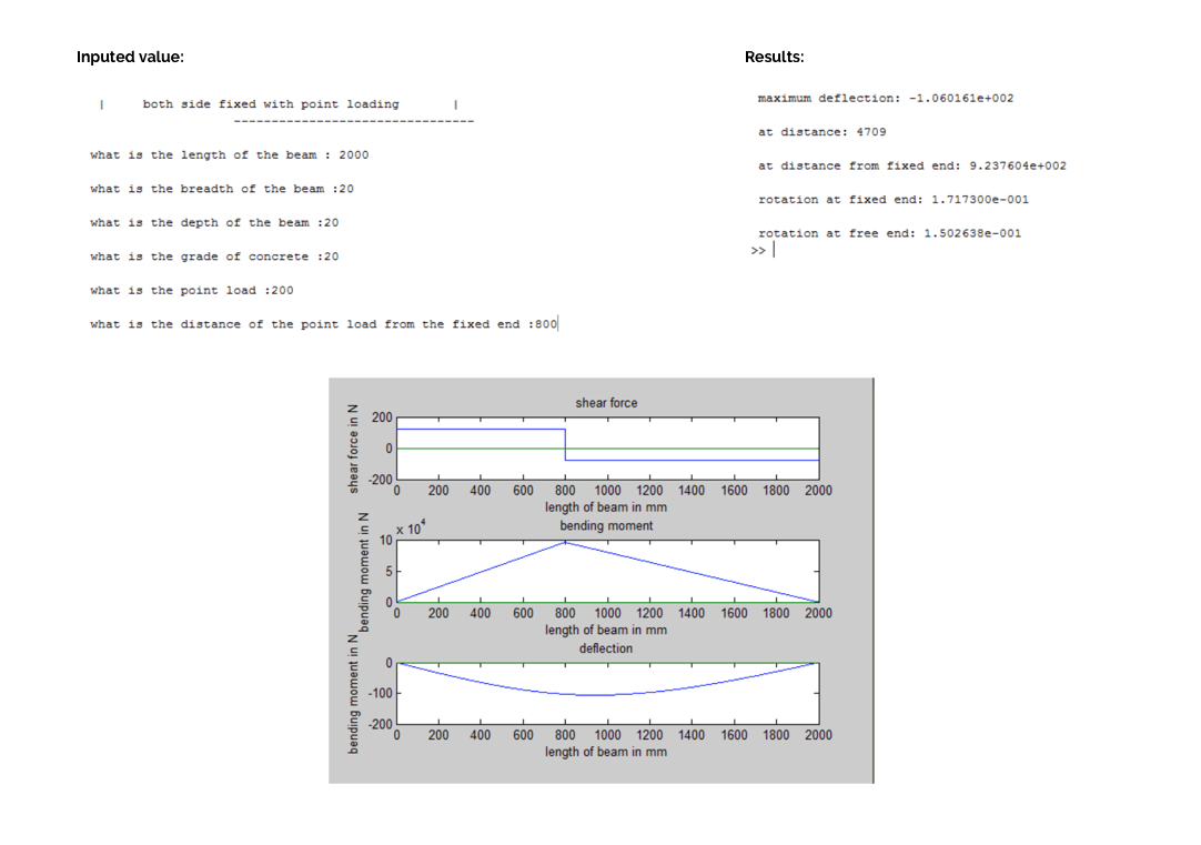
Point loading
A concentrated force applied at a specific location along the beam. The software computes the resulting internal forces and plots the shear and moment distribution.
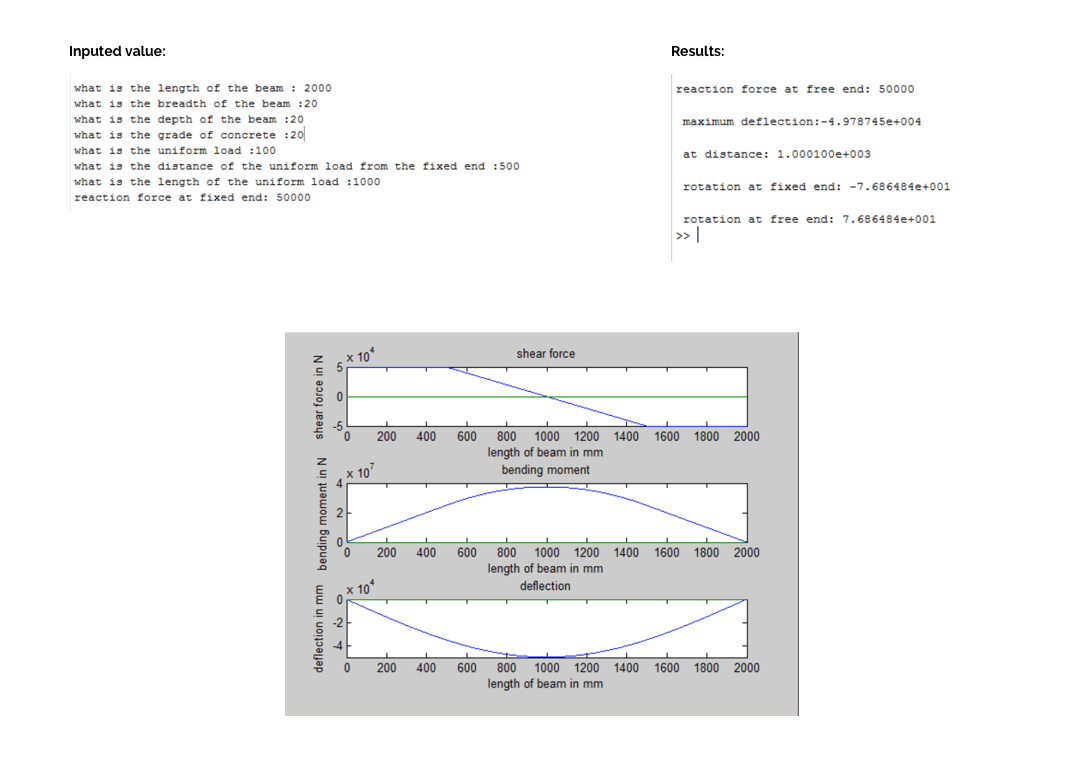
Uniform loading
A distributed force spread evenly across the beam's span. This is the most common loading condition in real structures, representing floor loads, snow loads, or self-weight.
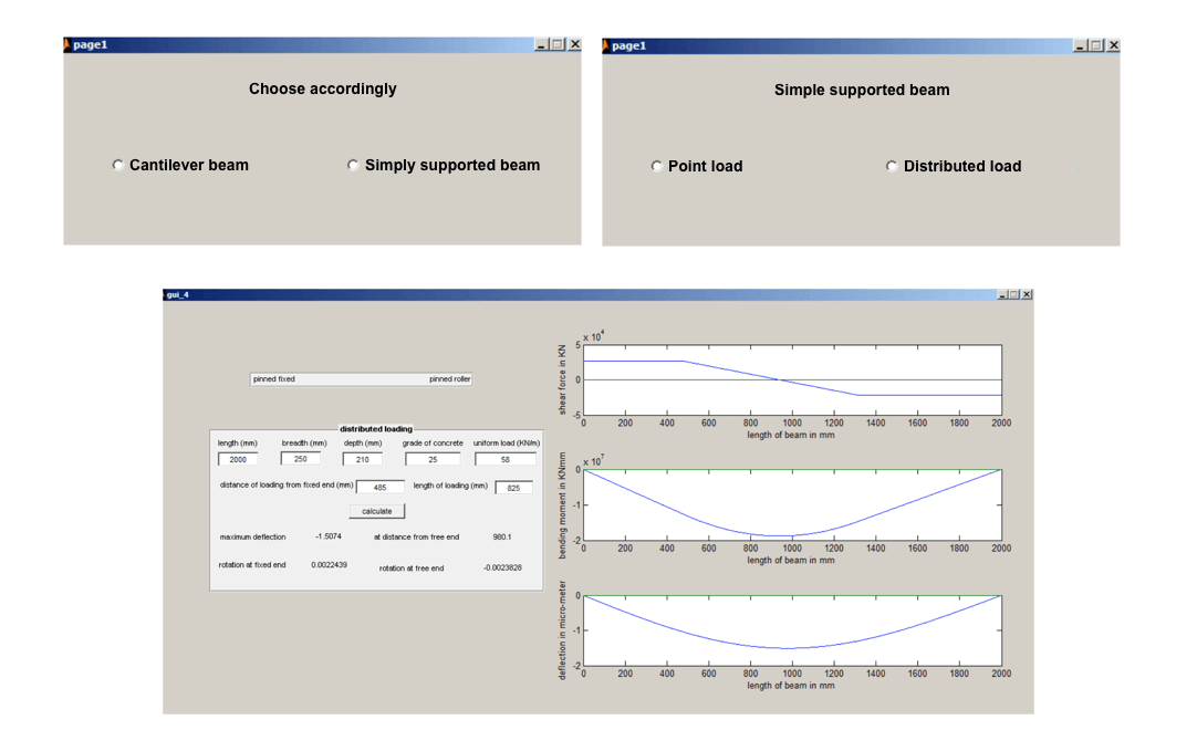
User interface
Beyond the computational engine, I built a graphical interface in MATLAB that allows users to input beam parameters, select loading conditions, and view results without writing any code. The goal was to make structural analysis accessible to students and engineers who needed quick answers without setting up complex simulations.
Outcome
The tool successfully handles cantilever, simply supported, and other standard beam types under arbitrary loading combinations. At the time it was built, it was among the few tools that provided this level of analysis with such a straightforward interface.
The project was an exercise in combining structural engineering theory with computational thinking. It reinforced a principle that has guided my work since: complex domains become more accessible when you build the right tools around them.